Understanding vfd circuit Variable frequency drive circuit diagram pdf Variable frequency drive circuit diagram
Single Phase Variable Frequency Drive VFD Circuit | Circuit diagram
Single phase variable frequency drive vfd circuit Vfd variable frequency circuits simplifying Variable frequency vfd
Principles of operation
Using single phase to power 3 phase vfdSingle phase variable frequency drive vfd circuit Frequency variable drive circuit vfd single phase diagram circuits used voltage motor hz power adjustment controls optimizing r1 r8 bothVfd variable pwm.
Motor vfd drive variable frequency phase single usingVariable frequency drive circuit diagram pdf » wiring core Single phase variable frequency drive vfd circuit – homemade circuitVfd energy vsi induction variable frequency approach.

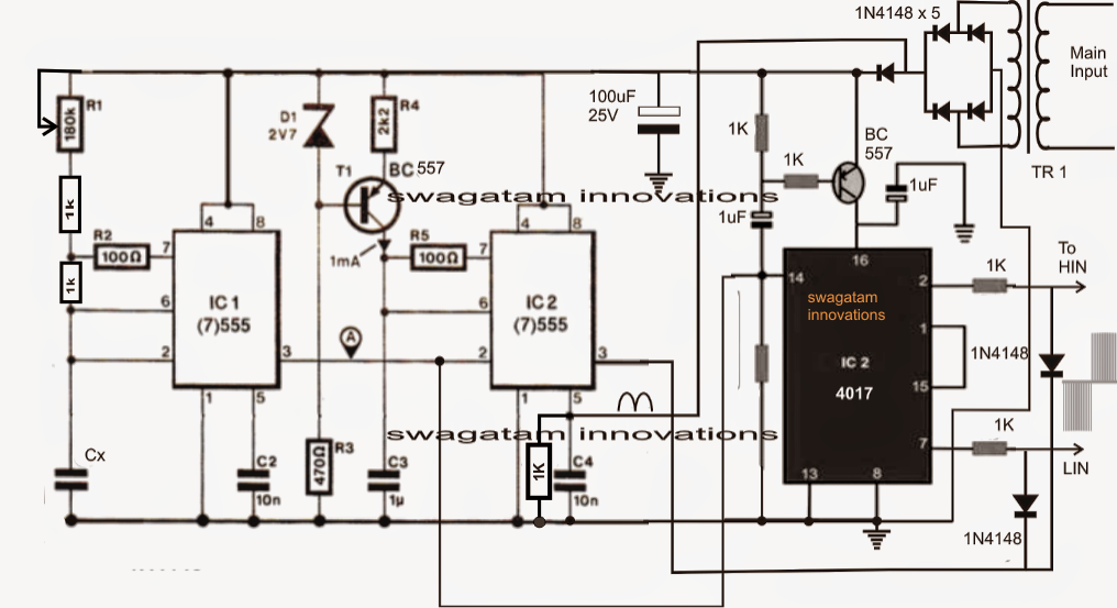
The post explains a simple variable frequency drive or vfd circuit
Variable frequency driveVfd (variable frequency drive) Vfd control wiring diagram3 phase variable frequency drive circuit diagram.
Vfd phase frequency circuit circuits ful eliminatedSingle phase variable frequency drive schematic On video motor connection with vfd wiring diagramSingle phase variable frequency drive vfd circuit.

Using variable frequency drive (vfd) for single phase motor
Frequency variable drive circuit vfd single phase diagram circuits used motor voltage hz choose board post power adjustment simpleVariable frequency drive motor ac components dc inverter control voltage bus principle working motors converter sections three figure main Phase circuits vfd circuit diagram variable frequency drive single wiring electrical motor speed homemade diy projects schematic ac control powerVfd circuit phase single frequency drive variable circuits homemade projects diagram board connection motor speed driver supply line motors 12v.
Vfd diagram wiring motor circuit ac drives operation panel drive variable frequency schematic principles dc pulse width inverter convert phaseWhat is variable frequency drive circuit: its operation, types and Variable speed drive block diagramVfd circuit drive types operation working gupta sourav jan.

Phase circuits vfd circuit diagram variable frequency drive single wiring electrical motor speed homemade diy projects schematic ac control power
Single phase variable frequency drive vfd circuitVfd circuit diagram schematic wiring motor understanding drive variable frequency components full rectifier vfds filter output fig resolution click picture Motor controllerVariable frequency drive.
Phase circuits vfd circuit diagram variable frequency drive single wiring electrical motor speed homemade diy projects schematic ac control powerSingle phase variable frequency drive vfd circuit Vfd frequency variable connectionSingle phase variable frequency drive vfd circuit – homemade circuit.

Variable frequency drive 3 phase
Drive vfd variable sine waveVariable frequency drive wiring diagram Single phase variable frequency drive vfd circuit(pdf) design, modeling analysis and performance evaluation of a single.
Single phase variable frequency drive vfd circuitVfd pwm circuit motor phase igbt diagram inverter vsd controller skema kecepatan induksi rangkaian drives frecuencia pengaturan module circuits Single phase variable frequency drive vfd circuitVariable frequency drives explained.

Variable Frequency Drive 3 Phase | Vfd Motor Control Circuit Diagram

VFD (Variable Frequency Drive) - Working, Types & Applications

Single Phase Variable Frequency Drive VFD Circuit | Circuit diagram

Single Phase Variable Frequency Drive VFD Circuit – Homemade Circuit

The post explains a simple variable frequency drive or VFD circuit

Variable Frequency Drive

on video Motor Connection with VFD Wiring Diagram - Cour electrique